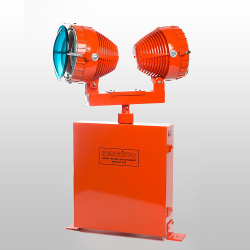
Heliport Lighting - Programmable LED Location & Identification Beacon
Available as three or single color units, using high brightness LEDs and advanced micro-electronics to provide a range of pre-programmed and user field-selectable operating modes with on-board switches to enable different maximum light output levels to be set and to enable control which quadrants of light are active
KEY FEATURES
- FAA L-802H Civil Helipad Beacon - 36 Flashes per Minute [FPM], 75ms pulse width
- US Army Helipad Pattern (as per TM 5-811-5) 36 Flashes per Minute, 50ms pulses White (double Peak) – Green - Yellow
- FAA L-802M Military Helipad Beacon - 17.3 FPM, 100ms pulse width
- 2 Location beacon modes:
- Modified ICAO pattern (short [2mS] and long [ 25mS] pulse) - 30 FPM
- 25 FPM UK CAA and Transport Canada timing compliant
- 2 Morse beacon modes: 4 - 6 WPM (Words Per Minute): 1, 2 and 3 character code options
- Rotating (simulated) and flashing beacon modes
SPECS
Electrical Characteristics: Operating voltage: 120-240VAC Average power consumption: Less than 90 watts Protection LED Lifetime (projected): >50,000 hours Relay contact output for alarm monitoring LED
Color Characteristics Standard: White: 6000oK/6500oK ‘Cool White’ Green: 528nm Yellow: 590nm
Options: Red 625nm; Red-Orange 617nm; Hyper Red 656nm or Deep Blue 455nm
Physical Characteristics: 8 inches tall 7.063" Bolt Circle Degree of protection: IP66 Operating temperature: -25oC to +50oC Storage temperature: -25oC to +80oC
Level Setting Switches: Maximum brightness to be set to 4 levels:- 100% of Maximum Level (Factory Set Default) 60% of Maximum Level 30% of Maximum Level 10% of Maximum Level
Quadrant Control:
There may be situations where an operator requires that the beacon is only visible from certain
directions (for example, to avoid dazzling pilots or causing a distraction).
Usually this would require the operator to fit screening or similar but with the FEC Programmable
Location & Identification Beacon this is simply achieved by disabling the relevant array(s) by means of
simple switches on the main circuit board.
To disable a particular array simply slide the switch to ON (Disable) using the tip of a ball point pen or
similar tool. The relevant array(s) will remain permanently disabled in all programming modes until the
switch(es) are turned off again.
As shipped, all of the arrays are enabled (all Array Disable switches – Off) giving the full 360o pattern as
shown 360 Quadrant 4:4 Arrays opposite.


